Encoding circuits for stabilizer codes and the Steane code
Yesterday we introduced the Steane code. One thing we did was mathematically construct the logical basis states for Steane code. A natural question to ask is, how does one create that state using a quantum circuit?
Gottesman's method to construct logical zero state of stabilizer codes
There is a very systematic method for creating the logical zero state using the stabilizer generator matrix [1]. The method is a three part process.
- Bring the generator matrix to standard form.
- Construct logical operators of the code.
- Use Gottesman's algorithm to determine the sequence of gates in the encoding circuit.
We are going to demonstrate the method using this matrix. I will do some of the work using a small python library I am writing to play with quantum stabilizer codes. It's called stac.
Let's load up the Steane code.
# I will need some of these helper libraries
import stac
from qiskit import QuantumCircuit, execute, Aer
from tabulate import tabulate
cd = stac.CommonCodes.generate_code('[[7,1,3]]')
stac.print_matrix(cd.gens_mat, augmented=True)
1. Bring the generator matrix to standard form
The matrix above is the generator matrix of the Steane code that we saw yesterday. It has generators/row, and columns, so physical qubits. And it encodes logical qubit.
We will now transform it to the standard form. What does this mean? Note that each row of represents a generator of the stabilizer group associated with the Steane code. We can manipulate the generators and qubits in the following way.
- We know from group theory that we can replace one of the generators with where is another generator, and we will have obtained a new generating set for the same group. Multiplying generators corresponds to adding rows of (why?).
- We can also reindex the generators, which corresponds to permuting the rows .
- We can also reindex the physical qubits, which corresponds to simultaneously permuting the columns on both sides of .
All of these operations on the generators don't change the code, only create a new representation of it. The corresponding operations on are simply those that we do when doing Gaussian reduction on a matrix. Recall that any matrix can brought into a reduced row echelon form (RREF), which is unique. We will use this fact to create the standard from of . The goal is to simplify the generators so they have as few Paulis in them as possible.
The standard form is obtained as follows. First bring the part of to RREF, remembering to permute columns on both sides. This reduces to Let be the rank of the part of . Then, the blocks have
- and rows respectively,
- and columns respectively.
If we then bring to RREF, due to the properties of the code, will reduce to Here, the columns of the blocks are of size , and respectively.
This is the standard form of . For the Steane code, it is as follows.
cd.standard_form()
stac.print_matrix(cd.standard_gens_mat, augmented=True)
2. Construct logical operators of the code
Yesterday, I presented two operators and called them the logical and operators. In fact, there are many different operators that can equivalently act as the logical and . Here, we use Gottesman's method to construct them. The claim is that [2], the logical s are the rows of the matrix Remember that some codes encode more than one logical qubit, so if a code encodes logical qubit, we will need logical s.
Similarly, the logical s are
We can read off these from , and for the Steane code, they are as follows.
cd.construct_logical_operators()
print("Logical X =", cd.logical_xs)
print("Logical Z =", cd.logical_zs)
Logical X = [[0 0 0 0 1 1 1 0 0 0 0 0 0 0]]
Logical Z = [[0 0 0 0 0 0 0 1 1 0 0 0 0 1]]
3. Use Gottesman's algorithm to determine the sequence of gates in the encoding circuit
Now we are ready to construct the encoding circuit for the zero state. It's a very simple algorithm. Let qubits be numbered 0-(n-1), let qubits 0-(n-k-1) be the ancilla qubits in state and the remaining qubits be where the unknown state is fed in. Here, we will let .
encoding_circuit = []
for i in range(k):
    for j in range(r, n-k):
        if logical_xs[i, j]:
            encoding_circuit.append(["cx", n-k+i, j])

for i in range(r):
    encoding_circuit.append(["h", i])
    for j in range(n):
        if i == j:
            continue
        if standard_gens_x[i, j] and standard_gens_z[i, j]:
            encoding_circuit.append(["cx", i, j])
            encoding_circuit.append(["cz", i, j])
        elif standard_gens_x[i, j]:
            encoding_circuit.append(["cx", i, j])
        elif standard_gens_z[i, j]:
            encoding_circuit.append(["cz", i, j])
One subtlety here is that instead of using the complex gate, we instead let , which is a real matrix. So, the place where we have to apply , we apply followed by .
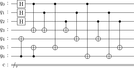
Executing this algorithm, we get the circuit as follows.
enc_circ = cd.construct_encoding_circuit()
stac.draw_circuit(enc_circ, output='latex')
# unfortunately, qiskit has a nasty habit of rearranging the gates.
We should check that this produces the right state. We should produce the state
We will use Qiskit to simulate to encoding circuit.
# I personally like displaying the output state in a nice way.
def simulate_circuit(circuit, n, head=None):
    if head is None:
        head = ['basis', 'amplitude']
    tab = [[bin(i)[2:][-1::-1].ljust(n,'0')] for i in range(2**n)]

    qc = QuantumCircuit.from_qasm_str(stac.circuit_to_qasm(circuit))
    job = execute(qc, Aer.get_backend('statevector_simulator'),
                  shots=1,
                  optimization_level=0)
    sv = job.result().get_statevector()

    amps = sv.data.real
    for i in range(2**n):
        tab[i].append(np.round(amps[i],3))

    smalltab = []
    for t in tab:
        if any(t[1:]):
            smalltab.append([' ' if val == 0 else val for val in t])

    print(tabulate(smalltab, headers=head))

simulate_circuit(enc_circ, cd.num_physical_qubits)
  basis    amplitude
-------  -----------
0000000        0.354
1111000        0.354
1100110        0.354
0011110        0.354
1010101        0.354
0101101        0.354
0110011        0.354
1001011        0.354
We can similarly, create the logical one state. There are two ways go about this. Either,
- We feed in the state into the circuit, or
- We use the logical to flip the logical zero state.
Let's do both.
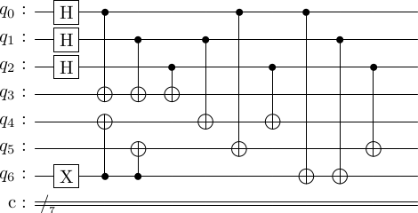
# Option 1
enc_circ_one = [['x', 6]] + enc_circ
stac.draw_circuit(enc_circ_one, output='latex')
simulate_circuit(enc_circ_one, cd.num_physical_qubits)
# looks good
  basis    amplitude
-------  -----------
0110100        0.354
1001100        0.354
1010010        0.354
0101010        0.354
1100001        0.354
0011001        0.354
0000111        0.354
1111111        0.354
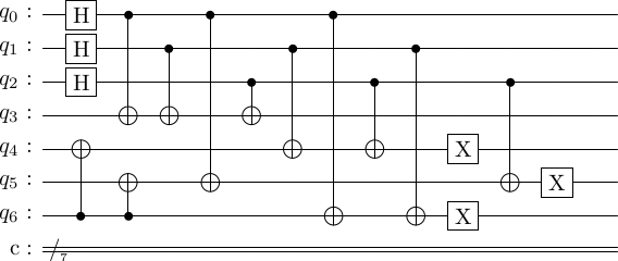
# Option 2. Use the logical X created above
enc_circ_flip = enc_circ + [['x', 4], ['x', 5], ['x', 6]]
stac.draw_circuit(enc_circ_flip, output='latex')
# anybody know how to fix qiskit's draw to respect the input ordering?
simulate_circuit(enc_circ_flip, cd.num_physical_qubits)
# looks good
  basis    amplitude
-------  -----------
0110100        0.354
1001100        0.354
1010010        0.354
0101010        0.354
1100001        0.354
0011001        0.354
0000111        0.354
1111111        0.354
Addendum
Actually, there is minor 'mistake' in Gottesman's encoding circuit algorithm. For some codes, if you feed in a basis states at the input, it's possible the created logical basis state is a eigenvectors of some of the stabilizer generators. This is not a real problem. On a real quantum computer, for real applications, we are unlikely to initialize our circuit in anything but the logical zero state. Instead, we create the states of interest by then manipulating the logical zero state using logical operations. However, there might be quantum information protocols where such unknown quantum states need to be encoded, where this fact is relevant.
In any case, we can fix this problem, by using the concept of destabilizers. But I will defer this discussion to a later time.
[1] D. Gottesman, Stabilizer Codes and Quantum Error Correction, arXiv:quant-ph/9705052.
[2] Gaitan, Frank, Quantum Error Correction and Fault Tolerant Quantum Computing (CRC Press, 2008).