Fault-tolerant syndrome measurements
Last time we studied a non-fault-tolerant version of syndrome measurements. Today, let's study a method that is fault-tolerant (FT), i.e. a single error in a block does not create more than one errors in the same or any other block.
Problem with the non-FT measurement circuit and a basic fix
Recall, that the problem was that an error e8 (see last post) or similar on a single ancilla qubit, caused multiple errors in the data block. This is intrinsic to coupling a single ancilla qubit to multiple data qubits. Therefore, a fault-tolerant syndrome measurement will require multiple ancilla qubits, one for each controlled operation between the ancilla and data qubits.
But we can't be naive about it. We need to remember the central principle of constructing syndrome measurement. We must only extract information about whether an error or which error has occured on the data qubits, without gaining any information about the logical state of the data qubits.
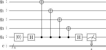
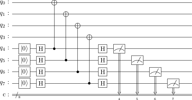
So we can't just replace the first of the following circuits with something like the second.
import stac

circ = stac.Circuit()
circ.append('R', 4)
circ.append('H', 4)
for i in range(4):
    circ.append('CX', 4, i)
circ.append('H', 4)
circ.append('MR',4)
circ.draw()

circ = stac.Circuit()
for i in range(4,8):
    circ.append('R', i)
    circ.append('H', i)
for i in range(4):
    circ.append('CX', 4+i, i)
for i in range(4,8):
    circ.append('H', i)
    circ.append('MR',i)
circ.draw()
Exercise: Compute the output state of the logical qubits, conditioned on the measurement outcomes and note that the measurement destroys any superposition the logical state is in.
There are many ways of doing FT measurements. We will analyze two of them.
A cat-state based FT-syndrome measurement circuit
To avoid extracting information about the logical circuit, one solution is to put the ancilla into a symmetrized state that doesn't store information about the logical state. This state is the "cat state", which is a state of the form
It can be created with a circuit of the following type.
cat_state_prep = stac.Circuit()
cat_state_prep.append('H', 0)
for i in range(3):
    cat_state_prep.append('CX', i, i+1)
cat_state_prep.draw()
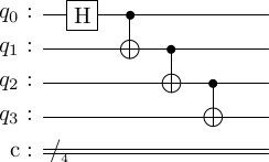
Exercise: Verify this circuit produces the cat state.
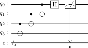
Exercise: The following circuit takes the cat state back to . What is the output state if we feed the state to the following circuit.
cat_state_unprep = stac.Circuit()
for i in range(2,-1,-1):
    cat_state_unprep.append('CX', i, i+1)
cat_state_unprep.append('H', 0)
cat_state_unprep.append('MR', 0)
cat_state_unprep.draw()
The cat state can then be used to measure the generators with the following circuit, where again, the first qubits are the data qubits, and the last four are ancilla.
cat_generator_measure = stac.Circuit()

# start with the cat state
cat_generator_measure.compose(cat_state_prep, 4)

# stabilizer measurement
cat_generator_measure.append('TICK')
for i in range(4):
    cat_generator_measure.append('CX', 4+i, i)
cat_generator_measure.append('TICK')

# reverse the cat state prep
cat_generator_measure.compose(cat_state_unprep, 4)

cat_generator_measure.draw()
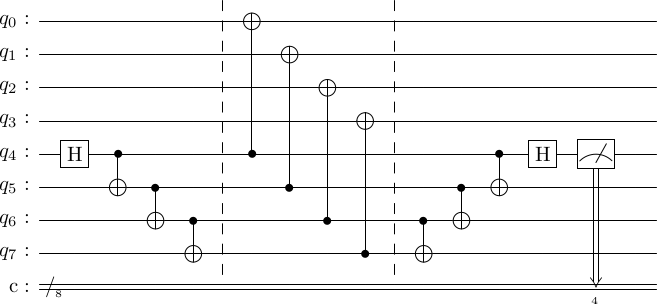
Does this procedure work? Suppose, the data qubits are in the state , which is either the logical state or a corrupted logical state .
Then, we start with . The state does not trigger any of the controls but the does. So, we get, Now, if
-
, then we get , and the remaining circuit on the ancillas reverses the cat state back to , and the measurement outcome is .
-
(where and anti-commute). Then the controlled operations evolve the state to . The remaining circuit on the ancillas transforms the ancilla state to . Hence, the measurement outcome is .
Hence, in this way, any errors on the logical state can be detected.
A note on resource usage
Recall that our non-tolerant procedure consumed m=6 ancillas (one for each of the stabilizer generators). We had to do 2 gates on each ancilla. And for the Steane code, four controlled operations per qubit. Hence, the final tally is 12 single-qubit gates, and 24 two-qubit operations on 6 ancillas.
Exercise: determine the resource consumption of the cat-state procedure. Note that we only showed how to measure one stabilizer generator.
Fault-tolerance of the cat-state procedure
Recall, that our analysis last time showed that a single-error on a code-qubit does not propagate down to ancilla and back up. This is a feature of the conjugation relations of the and operations. Hence, we don't have to worry about those.
Creating a cat state in a FT manner
A significant but a managable problem with the cat-state procedure is that an error during the cat state preparation will cause a faulty cat state to be used. To see this, let's label error locations on cat state preparation circuit.
cat_state_prep_errors = stac.Circuit()
cat_state_prep_errors.append('H', 0)
for i in range(4):
    cat_state_prep_errors.append_error(i)
for i in range(3):
    cat_state_prep_errors.append('CX', i, i+1)
cat_state_prep_errors.insert_errors(after_op='CX', error_types=['E', 'E'])
cat_state_prep_errors.draw()
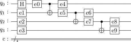
Stac has a nice function that simulates the impact of each of these errors on the final state. Let's use it.
cat_state_prep_errors.simulate_errors('qiskit', 'X')
  basis  no error    e0      e1      e2      e3      e4      e5      e6      e7      e8      e9
-------  ----------  ------  ------  ------  ------  ------  ------  ------  ------  ------  ------
   0000   0.707       0.707
   1000                       0.707                   0.707   0.707
   0100                                                               0.707
   1100                               0.707                                   0.707
   0010                                                                               0.707
   1110                                       0.707                                           0.707
   0001                                       0.707                                           0.707
   1101                                                                               0.707
   0011                               0.707                                   0.707
   1011                                                               0.707
   0111                       0.707                   0.707   0.707
   1111   0.707       0.707
In the above table, the second column is the final state if there was no error in the circuit. Each subsequent column shows the output state if one of the error was , as declared by our function.
Suppose that e1=$X$. Then, the input state would change to , and we would get . This is exactly what the fourth column tells us. The table also confirms what we trivially know, that certain errors should result in the same final state. For instance, e1 and e5 result in the same state. A list of errors that give a unique output state are the e1, e2, e3, e6, e8.
What about errors. The following simulation shows that errors after the gates, e0 and e4-e9, cause the cat state to acquire a relative minus sign.
cat_state_prep_errors.simulate_errors('qiskit', 'Z')
  basis    no error      e0     e1     e2     e3      e4      e5      e6      e7      e8      e9
-------  ----------  ------  -----  -----  -----  ------  ------  ------  ------  ------  ------
   0000       0.707   0.707  0.707  0.707  0.707   0.707   0.707   0.707   0.707   0.707   0.707
   1111       0.707  -0.707  0.707  0.707  0.707  -0.707  -0.707  -0.707  -0.707  -0.707  -0.707
What is the impact of these errors? It's clear that, besides e0, all other errors will cause an incorrect stabilizer generator measurement. However, we need to understand, like last time, if any of these errors cause more than one error in the data block.
To this end, we again use conjugacy relations, but in two steps. First let denote the output of the cat state preparation circuit when an error occurs, and let . Then, it is easy to evaluate by the conjugacy relations or by direct observations that
Now, observe the stabilizer generator measurement circuit show below.
cat_generator_measure_error = stac.Circuit()
cat_generator_measure_error.compose(cat_state_prep_errors, 7)

# stabilizer measurements.
cat_generator_measure_error.append('TICK')
for i in range(4):
    cat_generator_measure_error.append('CX', 7+i, i)


# append cat state unroll
cat_generator_measure_error.append('TICK')
cat_generator_measure_error.compose(cat_state_unprep, 7)

cat_generator_measure_error.draw()
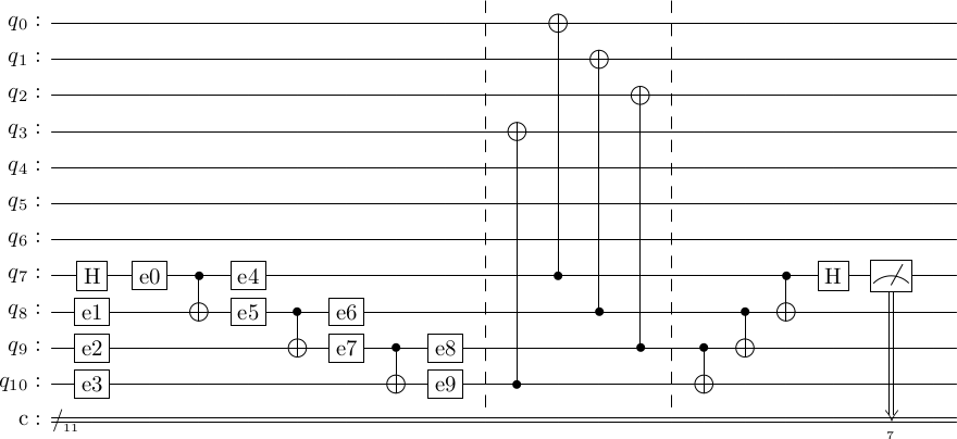
The lesson from last time was that for a gate, an error before the control qubit propagates to both control and target qubits, but errors don't.
This means that if
-
e1=$X$, then that is equivalent to (note the shift in coordinates from discussion above) after the cat state preparation. This gate will propagate up to the logical state and corrupt it. In particular, now there is one error on the logical state, which is acceptable by our FT criteria.
-
e2=$X$, then that is equivalent to just before the controlled operations. This is two errors that will both propagate up to the logical state, causing two errors on the logical state. This clearly voilates our FT criteria.
-
errors don't propagate for these type measurements. But will do so for the type measurements.
How do we fix this?
Fix for the cat state preparation circuit
The fix is quite simple. The cat states can be created in advance of the syndrome measurements. Then we check if an error has occured during the preparation of a cat state. If it has, we discard it and create a new cat state. In effect, this is a mini error-detection-and-discard step for the cat state preparation itself. The circuit for it is as follows.
cat_state_prep_fixed = stac.Circuit()
cat_state_prep_fixed.compose(cat_state_prep, 0)

# error detection on the cat state
cat_state_prep_fixed.append('TICK')
cat_state_prep_fixed.append('CX', 0, 4)
cat_state_prep_fixed.append('CX', 3, 4)
cat_state_prep_fixed.append('MR', 4)
cat_state_prep_fixed.draw()
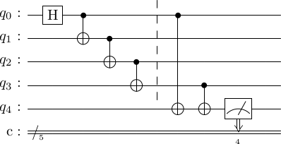
Basically, we are checking if the first and last qubits have the same value or not. Glancing at the table above, we note that if any of e1,e2,e3,e4,e5,e7,e9 are an , then we will detect it. Only, e6 and e8 remain undetected.
- This is a huge decrease in probability of errors on logical qubits.
- To deal with e6 and e8, we can't actually do just one round of syndrome measurements. We have to do it multiple times so we can detect such errors arising from the error-correction process itself. This repetition of the syndrome measurements is also important because of possible measurement errors at the end of syndrome measurement process.
Exercise: Analyze the effects of errors on the type generator measurements.
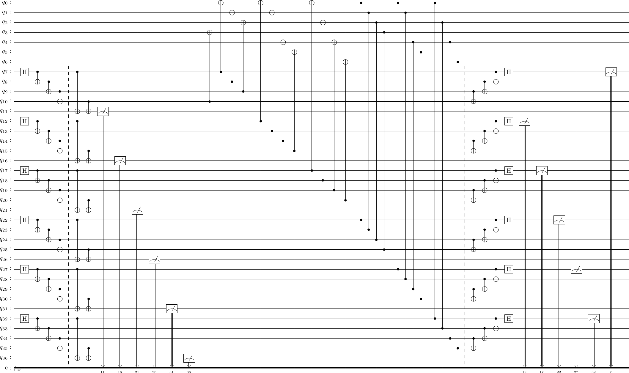
In this way, we have created a FT-method of measuring the stabilizers of the code. Stac can create this circuit for you in its entirety.
cd = stac.CommonCodes.generate_code('[[7,1,3]]')
cd.construct_syndrome_circuit('cat').draw()
A Shor-state based syndrome measurement circuit
Another proposal in literature to attain FT is to use the Shor state. This is a state is a superposition of all even-weighted basis states
This is actually not different from the cat-state process, except that the cat state process is done in the basis, while the Shor state process is done in the basis. Recall that if we sandwhich a with Hadamards its control and target flip, i.e. .
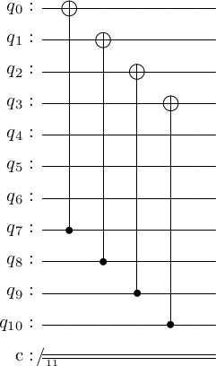
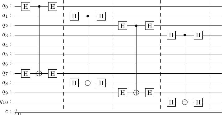
Using this idea, the gates in the generator-measurement can be flipped. For instance, . Using this the following two circuits are equal.
generator_measure = stac.Circuit()
for i in range(4):
    generator_measure.append('CX', 7+i, i)
generator_measure.draw()

generator_measure_flipped = stac.Circuit()
for i in range(4):
    generator_measure_flipped.append('H', i)
    generator_measure_flipped.append('H', 7+i)
    generator_measure_flipped.append('CX', i, 7+i)
    generator_measure_flipped.append('H', i)
    generator_measure_flipped.append('H', 7+i)
    generator_measure_flipped.append('TICK',0,10)
generator_measure_flipped.draw()
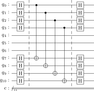
Syntactically, we can move all the at the start and end to get the following circuit.
generator_measure_nice = stac.Circuit()
for i in range(4):
    generator_measure_nice.append('H', i)
    generator_measure_nice.append('H', 7+i)
generator_measure_nice.append('TICK')
for i in range(4):
    generator_measure_nice.append('CX', i, 7+i)
generator_measure_nice.append('TICK')
for i in range(4):
    generator_measure_nice.append('H', i)
    generator_measure_nice.append('H', 7+i)
generator_measure_nice.draw()
Now, putting this circuit back in with the cat-state process, we get the following circuit.
shor_generator_measure = stac.Circuit()
shor_generator_measure.compose(cat_state_prep, 7)
shor_generator_measure.append('TICK')
shor_generator_measure.compose(generator_measure_nice, 0)
shor_generator_measure.compose(cat_state_unprep, 7)

shor_generator_measure.draw()
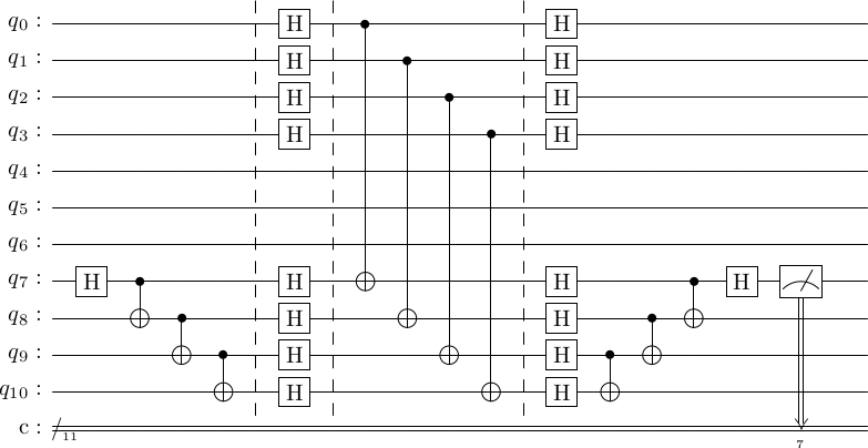
In this circuit, the cat-state prep followed by the gates is a circuit for preparing the Shor state. The analysis for this is as before with errors in the cat state resulting in a corrupted Shor state that can move errors into the logical state.
I don't see the value of this procedure as this has more gates than the cat-state process.